In this guide
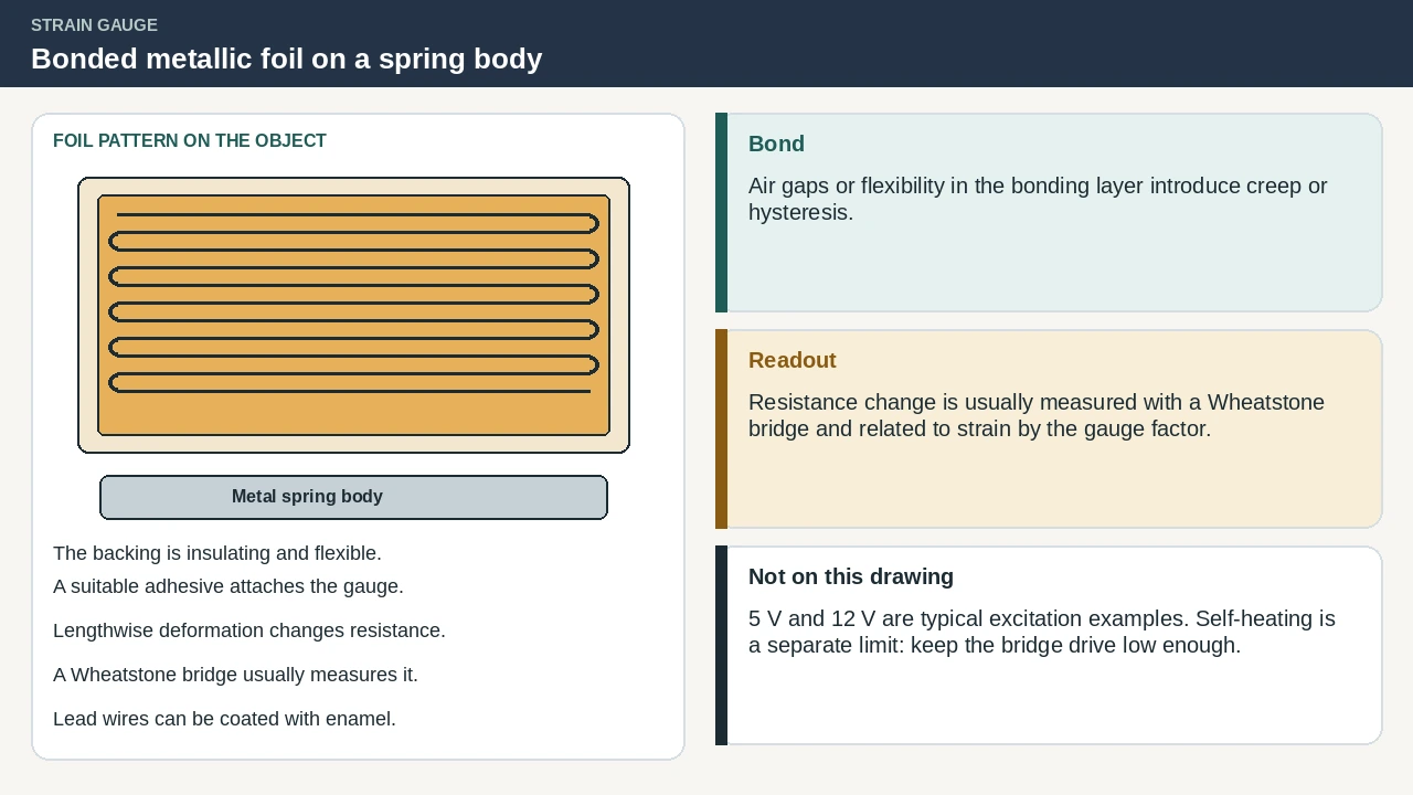
A strain gauge, also spelled strain gage, is a device used to measure strain on an object, while semiconductor piezoresistors serve small-strain sensing. The most common construction supports a metallic foil pattern on an insulating flexible backing attached to the surface with a suitable adhesive such as cyanoacrylate. As the object deforms, the foil deforms and changes its electrical resistance; a Wheatstone bridge usually measures that shift, and the gauge factor GF equals ΔR divided by RG divided by strain ε. Kistler notes that strain-gauge electrical resistance shifts upon even the smallest lengthwise deformation and can be determined with high precision and long-term stability in a Wheatstone bridge circuit. Proper adhesion is critical, because any air gaps or flexibility in the bonding layer introduce measurement errors known as creep or hysteresis, while quarter-bridge and half-bridge interconnecting leads must be treated in specific ways to reduce thermal errors.
Where bonded strain gauges fit across spring elements, force sensors, and stress tests
Resistive foil gauges instrument stiff materials including metals, ceramics, and composites. In pressure-sensor manufacturing, strain-gauge elements are commonly formed from silicon, polysilicon, metal film, thick film, and bonded foil. Because a Wheatstone bridge performs a difference measurement, measuring an unknown resistance can stand in indirectly for force, pressure, or temperature.
Kistler explains that a strain-gauge force sensor uses a metal measurement body or spring body generally fitted with four glued-on strain gauges: two aligned parallel to the force vector to measure length change, and two affixed transverse at a 90° offset to detect narrowing or thickening so two expand while two compress under load. Kistler states that strain-gauge force sensors measure static and quasistatic tensile and compression forces where longevity and thermal stability are required, that piezoelectric technology is better suited to dynamic forces, and that a Wheatstone bridge arrangement can be designed for a wide range of environments. Kistler describes its own static and quasistatic strain-gauge force sensors as measuring extremely precisely and practically drift-free.
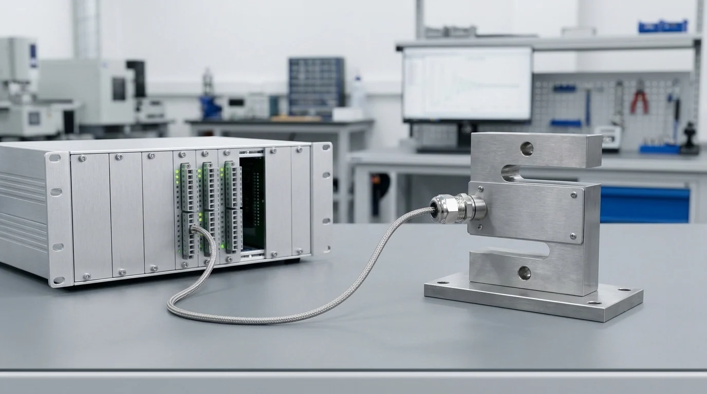
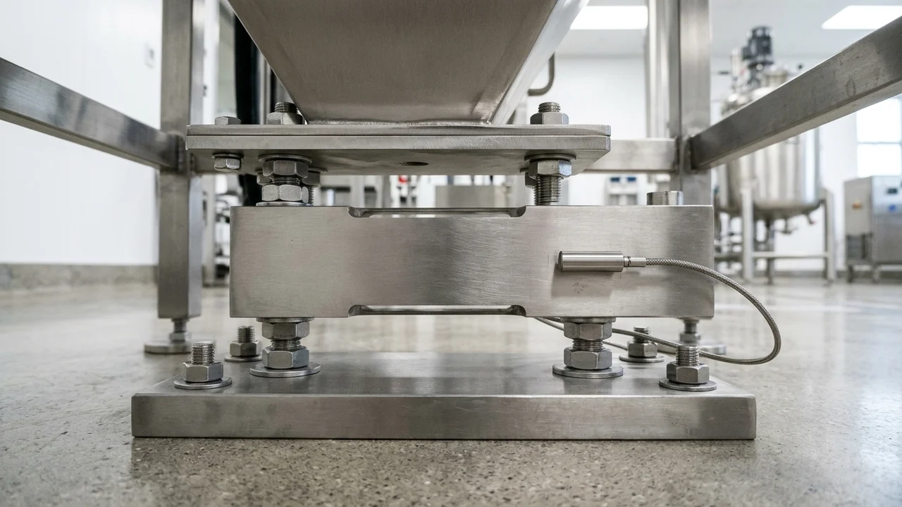
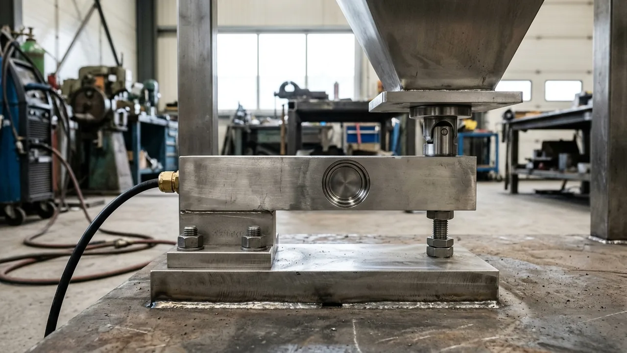
Across industrial load cells and controls, a load cell converts applied force into a signal, and a packaging machine still needs a controlled force path, appropriate electronics, and an identified calibration relationship before that signal is a useful weight. The strain-gauge load cell guide follows the path from the mounting points to the controller, where the elastic element deforms, a bridge turns the resistance change into a differential voltage, and the transmitter scales that voltage into a weight value. Terminal functions, mV/V electrical conversion, cable compensation, and manufacturer-specific wire colors—since wire colors are not a universal pinout—belong to the Wheatstone bridge wiring guide.
How lengthwise grid deformation changes foil resistance
Micro-Measurements defines strain as the change in length compared with the original length, and notes that although strain has no dimensions it is usually expressed as ε in units of in/in or mm/mm. When a strain gage is stretched or strained, Micro-Measurements states that its electrical resistance changes in direct proportion to strain, using a metallic foil grid pattern that maximizes the amount of foil subject to strain in parallel directions.
Electronic Design explains that etching a serpentine pattern into metal foil creates a relatively high resistance inside a compact space on a thin insulating substrate, with the long serpentine lines aligned parallel to a metal bar’s length when measuring bending. Almost all of a gage’s resistance resides in those long, thin pattern elements, while thickened turnarounds where the pattern bends reduce sensitivity across the grid—known as transverse sensitivity—even though all gages still exhibit transverse sensitivity and temperature dependencies.
Foil gauges typically have active grid areas of about 2–10 mm2, and with careful installation, the right gauge, and the right adhesive, strains up to at least 10% can be measured. In metals, the resistance shift comes mostly from geometric deformation, whereas in semiconductor materials the piezoresistive change of resistivity can be several orders of magnitude larger than the geometric effect.
Gauge factor and fractional resistance change before bridge amplification
Wikipedia defines the gauge factor GF as ΔR divided by RG divided by ε, where ΔR is the change in resistance caused by strain, RG is the resistance of the undeformed gauge, and ε is strain. Electronic Design defines the same quantity, written FG, as the relative change in resistance caused by the relative change in length.
For common metallic foil gauges, Wikipedia reports that the gauge factor is usually a little over 2. Electronic Design separately notes that the gage factor for metal foil gages typically ranges from 2 to 5, where a higher value corresponds to a more sensitive gage.
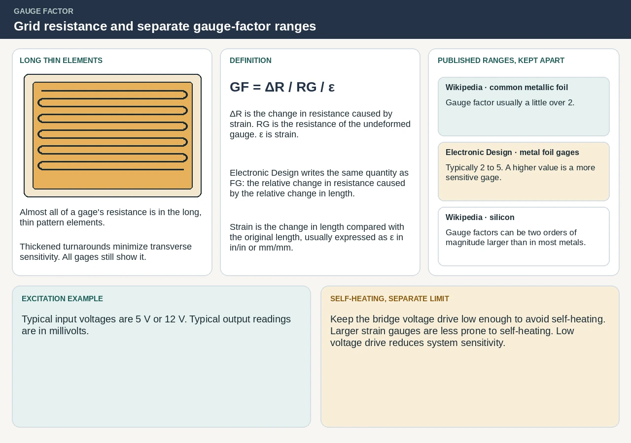
Micro-Measurements notes that the Wheatstone bridge became the sensing circuit of choice in most commercial strain-gage instrumentation because it detects the small resistance shifts produced as a gage follows minute surface dimensional changes under load. A Wheatstone bridge deflection reading is frequently used because reading a voltage difference across the bridge is usually faster than adjusting a resistance until the voltage reaches zero. Typical excitation input voltages applied to a gauge network are 5 V or 12 V, producing millivolt output readings. Good engineering practice keeps bridge drive voltage low enough to avoid strain-gauge self-heating; larger strain gauges are less prone to self-heating, while low drive voltage reduces overall system sensitivity.
Metallic foil alloys versus piezoresistive semiconductor gauges
The piezoresistive effect changes the electrical resistivity of a semiconductor or metal under mechanical strain; unlike the piezoelectric effect, it changes only electrical resistance and not electric potential. For small-strain measurements, semiconductor strain gauges (piezoresistors) are often preferred over foil gauges because they usually provide a larger gauge factor, although they tend to be more sensitive to temperature changes and more fragile than foil gauges. For silicon, gauge factors can be two orders of magnitude larger than those observed in most metals, and in precision measurements semiconductor gauges are harder to handle than metal gauges because of sensitivity to environmental conditions, especially temperature.
Most metallic strain gauges are made from constantan, a copper-nickel alloy usually consisting of 55% copper and 45% nickel that provides low thermal variation of resistivity across a wide temperature range. Constantan remains the oldest and most widely used strain-gauge alloy because its strain sensitivity is relatively insensitive to strain level and temperature, its resistivity yields suitable resistance in very small grids, and it combines a fairly low temperature coefficient of resistance with good fatigue life and relatively high elongation. However, constantan tends to exhibit continuous drift above 65 °C (149 °F), which should be taken into account whenever zero stability of the strain gauge is needed over hours or days. For very large strains of 5% (50,000 microstrain) or above, annealed constantan (P alloy) is normally selected, yet under high cyclic strains P alloy shows permanent resistivity change and a corresponding zero shift with each cycle and is not ordinarily recommended for cyclic strain applications.
Electronic Design notes that typical foil gages use constantan (A alloy) or Karma (K alloy) foil in self-temperature-compensated designs that minimize temperature effects. Various constantan and Karma alloys are formulated so temperature effects on the gauge’s own resistance largely cancel resistance changes from thermal expansion of the test object, which requires selecting an alloy matched to that substrate material because matching a gage to the wrong material can produce a large error.
| Strain Gauge Element | Primary Sensing Mechanism | Published Sensitivity and Alloy Properties | Documented Thermal and Application Limits |
|---|---|---|---|
| Constantan foil (A alloy) | Metallic foil resistance change mostly from geometry | Constantan usually consists of 55% copper and 45% nickel; Wikipedia’s figure for common metallic foil gauges is a gauge factor usually a little over 2 | Self-temperature compensation requires an alloy matched to the test material; continuous drift above 65 °C (149 °F) matters when zero stability is critical over hours or days |
| Annealed constantan (P alloy) | Ductile copper-nickel metallic foil grid | Selected for very large strains of 5% (50,000 microstrain) or above | Permanent resistivity change and zero shift under high cyclic strains; not ordinarily recommended for cyclic strain service |
| Karma foil (K alloy) | Metallic foil grid on a thin insulating substrate | Electronic Design’s gage factor for metal foil gages typically ranges from 2 to 5, and a higher value corresponds to a more sensitive gage | Self-temperature-compensated gages minimize the effect of temperature, and a potentially large error can result from matching a gage to the wrong material |
| Silicon / semiconductor piezoresistor | Piezoresistive resistivity shift orders of magnitude above geometry | Larger gauge factor than foil; silicon gauge factors can be two orders of magnitude larger than most metals | Preferred for small strain, but more fragile and harder to handle in precision work due to strong temperature sensitivity |
Carrier backing, adhesive cure, and moisture sealing for zero stability
Micro-Measurements states that proper bonding is essential for accurate strain measurement and lists strain-sensitive alloy, backing material (carrier), grid resistance, gage pattern, self-temperature-compensation number, and gage length as core selection parameters. In a conventional foil gauge, the etched foil sits on a thin insulating flexible backing bonded to the structural surface; any air gaps or flexibility in the bonding layer introduce creep or hysteresis. Linearity is an error whereby the sensitivity changes across the pressure range, commonly a function of the force-collection thickness selection for the intended pressure and the quality of the bonding, while hysteresis is an error of return to zero after a pressure excursion.
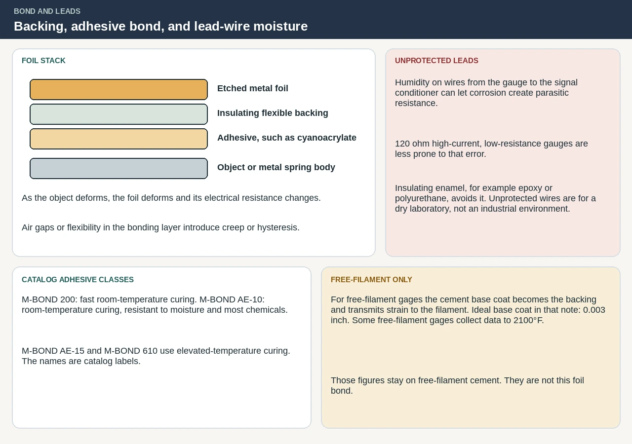
Micro-Measurements reports that its strain-gage adhesives protect against moisture and chemicals, distinguishing room-temperature general-purpose grades from elevated-temperature transducer cures in its catalog descriptions: M-BOND 200 is a fast room-temperature-curing general-purpose adhesive and M-BOND AE-10 is a room-temperature-curing general-purpose adhesive resistant to moisture and most chemicals, whereas M-BOND AE-15 uses moderately elevated-temperature curing for critical work including transducer gaging and M-BOND 610 uses elevated-temperature curing for wide-temperature stress analysis and precision transducers.
A foil gauge uses an insulating flexible backing, whereas for free-filament gages the cement base coat becomes the backing. For free-filament gages, Micro-Measurements explains that a ceramic cement base coat serves as both backing and strain-transmitting medium under the installer’s control: if too thick it cracks under strain, if too thin its insulation resistance to ground drops enough at extreme heat to affect signal stability, with an ideal 0.003 inch base coat in that note and valid data on some free-filament gages up to 2100°F.
In a NASA carbon/carbon composite study, foil-type high-temperature gages were more prone to failure during thermal cycling because the gage grid sheared, and an oxygen-acetylene bond could still be read at 540 degrees C with lower shear strength than the plasma-sprayed bond.
On industrial installations, leaving lead wires between the strain gauge and signal conditioner unprotected against humidity lets corrosion form parasitic resistance between the wires or to the substrate. High-current, low-resistance 120 ohm strain gauges are less prone to that humidity error, and coating the wires with insulating enamel such as epoxy or polyurethane prevents it because unprotected bare wires suit only dry laboratories rather than industrial environments.
Why quarter-bridge and half-bridge leadwires introduce thermal error
Micro-Measurements notes that in most surface stress-analysis applications, individual uniaxial or rosette gage elements connect independently in a quarter-bridge arrangement, and that the Wheatstone bridge also accommodates compensation for temperature-induced resistance shifts in the gage circuit. Electronic Design, quoting an HBM strain gage handbook, explains why transducer full bridges behave differently: in a full bridge where all four gages measure strain on a transducer, the four gages sit very close together with short interconnecting leads that have little influence on thermal performance, whereas quarter-bridge and half-bridge interconnecting leads must be treated in specific ways to reduce thermal errors.
For gauges without self-temperature compensation, an identical dummy gauge can be bonded to an unstrained sample of the same material placed in thermal contact with the specimen and wired into an adjacent Wheatstone bridge arm so thermal shifts cancel. Electronic Design cautions that in a quarter-bridge with a compensating gage, keeping that second gage under the exact same environment while experiencing zero strain may not be practical. On a bending beam, Electronic Design notes that mounting two measuring gages, one on the top and one on the bottom, in bridge positions 1 and 3 doubles the bridge output, and that this is a half-bridge in which each gage must still be compensated as in the quarter-bridge circuit. On carbon/carbon composites at 540 degrees C, NASA reported that a BCL-3 gage showed gage-to-gage scatter in total apparent strain of typically less than 500 microstrain from a total of 17000 microstrain, with negligible variation in drift rate from gage to gage, and that when two of those gages are placed in adjacent bridge legs and both see the temperature change, neither illustrated half-bridge apparent-strain curve exceeded 250 microstrain.
Temperature effects on lead wires themselves are cancelled with a 3-wire bridge or a 4-wire ohm circuit, also called a 4-wire Kelvin connection. Electronic Design also points out that voltage drops across excitation leads subtract from the source and reduce effective gage factor—the same two-wire resistance measurement error solved by four-wire Kelvin techniques. For the bridge equation, cable compensation, and the warning not to rely on a remembered colour convention from another brand, continue with the four-wire and six-wire Wheatstone bridge wiring guide.
Strain gauge bonding and leadwire verification checklist
Use this engineering checklist to audit grid selection, adhesive cure, and lead protection before attributing zero drift to downstream electronics:
- Grid alloy and thermal expansion match: Confirm constantan (A alloy) or Karma (K alloy) self-temperature compensation is matched to the substrate material’s thermal expansion, account for continuous constantan drift above 65 °C (149 °F) when multi-hour or multi-day zero stability matters, and avoid annealed constantan P alloy in cyclic strain service.
- Carrier and bond: Align the metallic foil grid, which maximizes the foil subject to strain in parallel directions, on stiff metals, ceramics, or composites, and treat air gaps or flexibility in the bonding layer as sources of creep or hysteresis. Linearity, an error whereby sensitivity changes across the pressure range, is commonly a function of force-collection thickness selection for the intended pressure and of bonding quality, and hysteresis is an error of return to zero after a pressure excursion.
- Adhesive catalog classes: Separate room-temperature general-purpose adhesives such as M-BOND 200, with fast room-temperature curing, and M-BOND AE-10, which is highly resistant to moisture and most chemicals and also room-temperature curing, from M-BOND AE-15, with moderately elevated-temperature curing for transducer gaging, and M-BOND 610, with elevated-temperature curing for wide-temperature stress analysis and precision transducers, and keep that foil-gauge list distinct from the free-filament cement base coat that becomes the backing.
- Moisture sealing and partial-bridge leads: Protect the wires from the strain gauge to the signal conditioner with insulating enamel such as epoxy or polyurethane. High-current, low-resistance 120 ohm strain gauges are less prone to the humidity error, and strain gauges with unprotected wires may be used only in a dry laboratory environment but not in an industrial one. Cancel temperature effects on the lead wires with a 3-wire bridge or a 4-wire Kelvin connection, treat quarter-bridge and half-bridge interconnecting leads to reduce thermal errors, and keep the Wheatstone bridge voltage drive low enough to avoid self-heating.
For complete sensor assemblies, review the load cells and controls overview and the packaging strain-gauge load cell guide.
Sources
- Wikipedia — Strain gauge
- Wikipedia — Constantan
- Wikipedia — Piezoresistive effect
- Wikipedia — Wheatstone bridge
- NASA Technical Reports Server — High-Temperature Strain Gage Apparent Strain Compensation on Carbon/Carbon Composites
- Kistler, Strain Gauge Force Sensors Technical Overview
- Micro-Measurements, What Is a Strain Gage and Strain Gage Adhesives Technical Reference
- Electronic Design, Gauging the Strain (including HBM Strain Gage Handbook quotation)